Output Devices
Assignment
Add an output device to a microcontroller board you've designed and program it to do something.Learning Outcomes
Demonstrate workflows used in circuit board design and fabrication.Implement and interpret programming protocols.
Design Process
To begin off this week, I thought about my final project and what types of electronics I would need for it. In my final project I am going to need a way for the temperature to be monitored and displayed. This requires me to have a temperature sensor and some sort of display. I decided to start off by building the hello.LCD.44 board. I followed the design steps that I used in Week 6 on how to add different components in Eagle and how to lay out the traces for the Roland Modela machine. After loading the traces onto the Roland and milling it out, I stuffed the board with the correct components, those being:1. ATtiny44 Microcontroller
2. 20MHz Resonator
3. 5V Regulator
4. 1 micro farad capacitor
5. 1 2x5 header
6. 1 2x3 header
7. 1 2x2 header
8. 3 Resistors, Values: 100k, 10k, and 1k
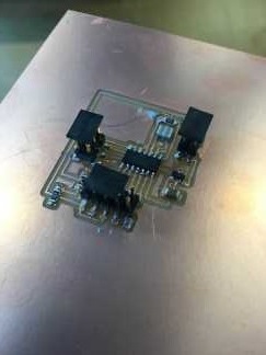
After stuffing the board I had the following:
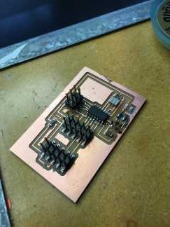
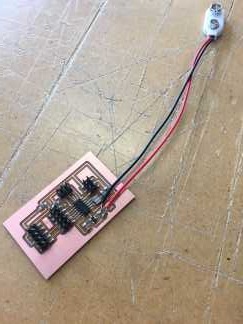
However, once I had finished I realized we only had ribbon cable with 9 wires in it. To fix this problem I went back into eagle and added another 2x5 header. This would allow me to use two 2x5 plugs and use 5 wires in each plug. After milling out the board and stuffing it I came up with the second iteration of my output board:
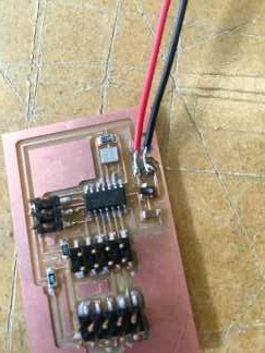
As you can see, another one of the changes I made was getting rid of the 2x2 header that supplies the power. I manually soldered the connections on, but I guessed wrong on the wiring and ended up frying the 5V regulator. It turned a really bright orange as it fried though, so that was cool. When trying to take off the now destroyed regulator, I ended up pulling off some of the copper traces. Damn. Time to mill out a new board again. After a third time of milling out this board and stuffing it I finally ended up with a good working board. The following pictures show the final board that I used to program the lcd:
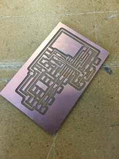
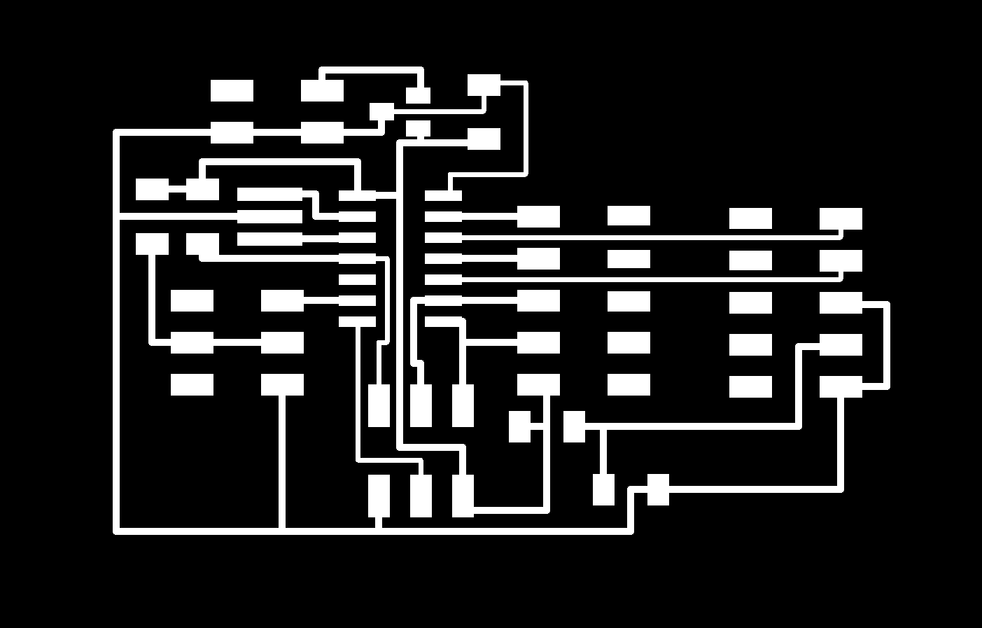
Below are also the pictures of my final trace for the board and outline:

Programming in Arduino
Before programming the board, Steven Fett had some female header wires that would be easier to use than the ribbon cable. Using these type of wires would allow me to change the wires around in case I wired some things wrong. To begin the programming process I decided to use the AVR mkII and loaded the Hello World example code provided by Arduino. I plugged the AVR mkII into the board and applied a power source to the board. The AVR mkII gave a green light which was a good sign that meant it was able to connect to the board. Before uploading the code, I tried burning the bootloader to the board. This did not work however. I kept getting the following error:avrdude: stk500v2_recv_mk2: error in USB receive
avrdude: stk500v2_recv_mk2: error in USB receive
avrdude: usbdev_send(): wrote -116 out of 1 bytes, err =
avrdude: stk500_send_mk2(): failed to send command to serial port
Error while burning bootloader.
I kept trying different things to get this error to go away and it seemed like everything I tried wouldn't work. I talked with Wendy Neale about this problem and she suggested that I try using the FabISP instead of the AVR mkII, as people in the past seemed to have problems with the mkII as well. Once I had the FabISP hooked up with my board, I tried burning the bootloader and... SUCCESS! The bootloader burned to the board no problem this time.
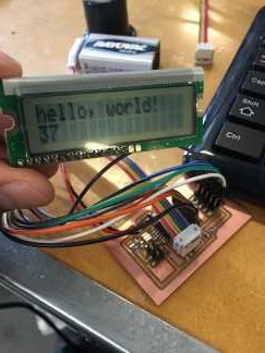
Now that I had the bootloader burned to the board it was time to upload the code. I tried just uploading the code as is from Arduino, but it did not work and all I had were black bars across the screen of the LCD. I then realized I had the pin numbers wrong in the code. Once I changed those I tried uploading the code again and luckily I saw "hello, world" and a timer on the LCD. Very happy with this result. Below are the pictures of the LCD working. I also had fun and sent my girlfriend a message on the LCD as well.
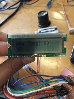
One thing I noticed though was that if the LCD was set down wrong or a wire became loose, I would get really weird characters on the screen. Something like the picture below:
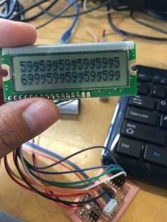
To fix this I would just unplug and re-plug the battery back in and the LCD would then work fine.
Lessons Learned
1. Overall, I am beginning to enjoy electronics more, even though this week probably took the longest for me to complete out of the electronics weeks.2. Keep working at something and don't be afraid to ask for help.
3. Take BREAKS if getting frustrated. Definitely helped in this weeks assignment.
Project Files
1. Hello World Schematic2. Hello World Board
3. Arduino, Hello World Code